AutoCAD 允许将 SPLINE 实体存储在仅由
拟合点,问题是,这样的样条定义有无限
数值正确的解决方案,Autodesk 不提供必要的
从给定的拟合点计算所需参数的信息。
tl;dr - 缺失的信息是估计的起点和终点切线
全局 B 样条输入切线的方向和幅度
用末端导数插值,有人可以帮助计算这个值吗?
Complete source code on github.
我使用 BricsCAD 进行测试,但“Trueview 2020”显示相同的结果。
1. 场景
只给出拟合点,使用全局曲线插值,没有任何约束
获取由控制顶点定义的样条:
# First spline defined by control vertices interpolated from given fit points
s = global_bspline_interpolation(points, degree=3)
msp.add_spline(dxfattribs={'color': 4, 'layer': 'Global Interpolation'}).apply_construction_tool(s)
# Second spline defined only by fit points as reference
spline = msp.add_spline(points, degree=3, dxfattribs={'layer': 'BricsCAD B-spline', 'color': 2})
doc.saveas(DIR / 'fit-points-only.dxf')
BricsCAD 从拟合点插值的样条与插值定义的样条不匹配
控制顶点:
2. 场景
除了拟合点,我还在 DXF 文件中存储了起点和终点切线值。
插值是通过具有末端导数的全局曲线插值完成的
(Piegl & Tiller:“The NURBS Book” - 第 9.2.2 章)。
我选择了一个任意角度(100 度)作为起点和终点切线,切线
幅度是通过“总弦长”方法估计的。
m1, m2 = estimate_end_tangent_magnitude(points, method='chord')
start_tangent = Vector.from_deg_angle(100) * m1
end_tangent = Vector.from_deg_angle(-100) * m2
# First spline defined by control vertices interpolated from given fit points and end-tangents
s = global_bspline_interpolation(points, degree=3, tangents=(start_tangent, end_tangent))
msp.add_spline(dxfattribs={'color': 4, 'layer': 'Global Interpolation'}).apply_construction_tool(s)
# Result matches the BricsCAD interpolation if fit points, start- and end
# tangents are stored explicit in the DXF file.
# Second spline defined by fit points as reference
spline = msp.add_spline(points, degree=3, dxfattribs={'layer': 'BricsCAD B-spline', 'color': 2})
# set explicit start- and end tangent as unit vectors
spline.dxf.start_tangent = Vector.from_deg_angle(100)
spline.dxf.end_tangent = Vector.from_deg_angle(-100)
doc.saveas(DIR / 'fit-points-and-tangents.dxf')
BricsCAD 插值的样条现在与由
插值控制顶点:
现在我知道插值方法是正确的,我只需要从拟合点渲染相同的样条
因为 BricsCAD 是从拟合点推断出的方向和大小的端切线。
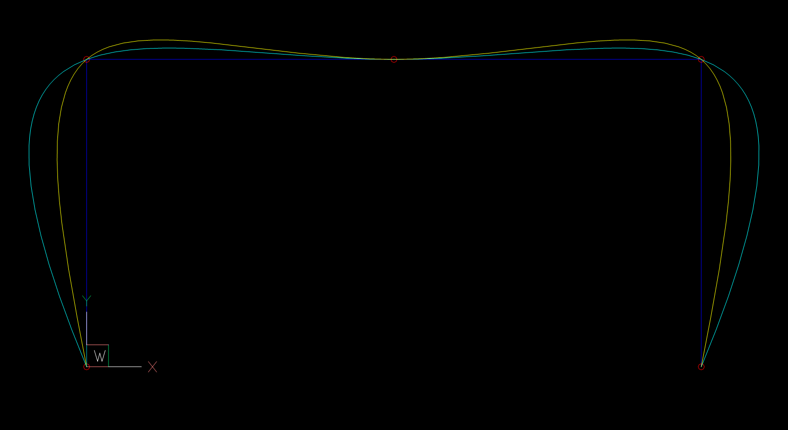
3. 场景
我需要控制顶点来渲染 B 样条,但是开始和
端切线不像场景 1 那样存储在 DXF 文件中。
需要估计起点和终点切线,最佳结果为:
来自“The NURBS Book”的“5 Point Interpolation”,Piegl & Tiller
tangents = estimate_tangents(points, method='5-points')
# Estimated tangent angles: (108.43494882292201, -108.43494882292201) degree
m1, m2 = estimate_end_tangent_magnitude(points, method='chord')
start_tangent = tangents[0].normalize(m1)
end_tangent = tangents[-1].normalize(m2)
# First spline defined by control vertices interpolated from given fit points and end-tangents
s = global_bspline_interpolation(points, degree=3, tangents=(start_tangent, end_tangent))
msp.add_spline(dxfattribs={'color': 4, 'layer': 'Global Interpolation'}).apply_construction_tool(s)
# Second spline defined by fit points as reference, but without explicit start- and end
# tangents to see if my estimations are correct.
msp.add_spline(points, degree=3, dxfattribs={'layer': 'BricsCAD B-spline', 'color': 2})
doc.saveas(DIR / 'tangents-estimated.dxf')
令人惊讶的是估计是不正确的,BricsCAD 样条的切线角为
101.0035408517495 和 -101.0035408517495 度。

真正令人讨厌的部分是,如果我使用 BricsCAD 角度作为输入,
样条仍然不匹配,所以我假设切线幅度
估计与场景 2 不同。
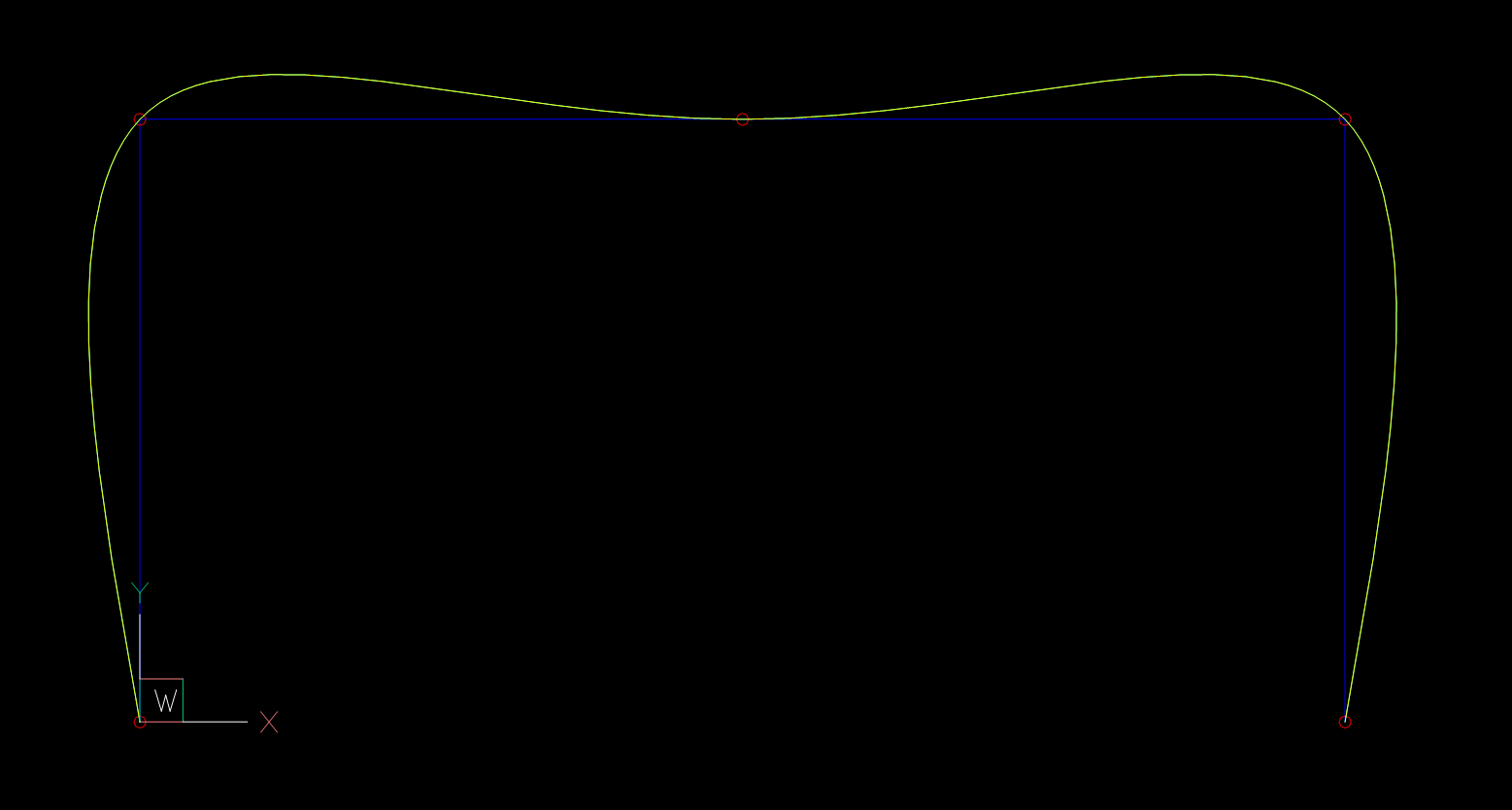
4. 理论检查
以下值是根据 BricsCAD 保存的 DXF 文件计算得出的
和 SPLINE “方法”从“拟合点”切换到“控制顶点”。
根据这些数据,我计算了切线角度和大小,
tangent vector = 2nd control vertex - 1st control vertexrequired_angle = 101.0035408517495 # angle of tangent vector in degrees
required_magnitude = m1 * 1.3097943444804256 # magnitude of tangent vector
start_tangent = Vector.from_deg_angle(required_angle, required_magnitude)
end_tangent = Vector.from_deg_angle(-required_angle, required_magnitude)
s = global_bspline_interpolation(points, degree=3, tangents=(start_tangent, end_tangent))
msp.add_spline(dxfattribs={'color': 4, 'layer': 'Global Interpolation'}).apply_construction_tool(s)
msp.add_spline(points, degree=3, dxfattribs={'layer': 'BricsCAD B-spline', 'color': 2})
doc.saveas(DIR / 'theory-check.dxf')
现在样条再次匹配:

插值函数是“总弦长”。
m1*1.3097943444804256 ,但它不是一个恒定的因素。
最大的问题是:如何估计方向和大小的起点和终点切线
像 AutoCAD 或 BricsCAD 用于仅由拟合点定义的样条曲线?
提前致谢,
曼弗雷德
最佳答案
SPLINE 实体可以有 可选 起始切线 x,y,z 的组代码为 12,22,32,结束切线 x,y,z 的组代码为 13,23,33。我检查了 netDxf 项目的源代码,如果仅使用拟合点来定义样条,则开始和结束切线值 将被指定 .
从 AutoCAD 2012 DXF Reference for SPLINE 实体:
12 Start tangent—may be omitted (in WCS) DXF: X value; APP: 3D point
22, 32 DXF: Y and Z values of start tangent—may be omitted (in WCS)
13 End tangent—may be omitted (in WCS) DXF: X value; APP: 3D point
23, 33 DXF: Y and Z values of end tangent—may be omitted (in WCS)
昨天我们和我的同事在 Autocad 2020 中创建了一些 DXF 文件,包括拟合点样条。导出到 DXF 后,样条由控制点和节点定义。所以我猜测拟合点已经过时或仅用于 UI。
关于autocad - AutoCAD 如何计算仅由拟合点定义的样条曲线的端切线?,我们在Stack Overflow上找到一个类似的问题: https://stackoverflow.com/questions/62472305/