我正在使用 AM335x 上的一个 PRU 单元来驱动 BeagleBone(GPIO1_2、GPIO1_3、GPIO1_6、GPIO1_7)上的 4 个 GPIO 引脚,并且我想同步边缘转换(我的完整源代码在底部)。
使用 Beaglebone 在引脚上设置输出 HI,将地址 0x4804c194 处的相应位设置为 1,然后将其设置为 LO,将地址 0x4804c190 处的位设置为 1。所以我的 PRU 汇编代码首先设置输出 HI 位,然后设置输出 LO 位:
 MOV r4, GPIO1 | GPIO_CLEARDATAOUT
 MOV r5, GPIO1 | GPIO_SETDATAOUT
 ...
 ...
//Loop the following:
MAIN_LOOP:
    LBCO r2, CONST_PRUDRAM, r1, 8//Read in LO and HI data into r2/r3
    SBBO r3, r5, 0, 1  //Write HI data
    SBBO r2, r4, 0, 1  //Write LO data
    ADD r1, r1, 8
    QBEQ EXIT, r1, 112  //Done?  Exit
    QBA MAIN_LOOP
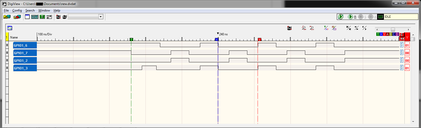
由于运行每个周期需要多少个周期,LO 周期明显长于 HI(50ns 对 110ns)。不幸的是,我太新,无法发布图片,here is a link to a logic analyzer screenshot from the previous code
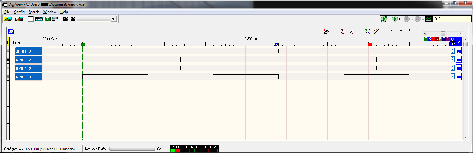
为了平衡超时,我交替设置 HI 和 LO 位,使周期在 80ns 处相等,但 HI 和 LO 转换彼此偏移 80ns:
 MOV r4, GPIO1 | GPIO_CLEARDATAOUT
 MOV r5, GPIO1 | GPIO_SETDATAOUT
 ...
 ...
//Loop the following:
MAIN_LOOP:
    LBCO r2, CONST_PRUDRAM, r1, 8 //Read in LO and HI data into r2/r3
    SBBO r3, r5, 0, 1  //Write HI data
    SBBO r2, r4, 0, 1  //Write LO data
    ADD r1, r1, 8
    QBEQ EXIT, r1, 112
    QBA MAIN_LOOP2

MAIN_LOOP2:
    LBCO r2, CONST_PRUDRAM, r1, 8 //Read in LO and HI data into r2/r3
    SBBO r2, r4, 0, 1  //Write LO data
    SBBO r3, r5, 0, 1  //Write HI data
    ADD r1, r1, 8
    QBEQ EXIT, r1, 112
    QBA MAIN_LOOP
Here too is a logic analyzer screenshot of the previous code.
所以我的问题是如何让边缘转换同时发生? IE。如果比较 GPIO1_6 和 GPIO_7,屏幕截图的中心是 GPIO1_7 转换为 LO 时的 200ns,然后是 50ns BEFORE,GPIO1_6 转换为 HI,我希望它们同时转换。我不介意放慢速度来完成这个。
这是我的源代码:
文件:main.p
.origin 0
.entrypoint START

#include "main.hp"

#define GPIO1 0x4804c000
#define PINMUX 0x44E10800

#define GPIO_CLEARDATAOUT 0x190
#define GPIO_SETDATAOUT 0x194
#define GPIO_DIRECTION 0x134
#define GPIO_DIRECTION2 0x142


START:
    //clear STANDBY_INIT bit
    LBCO r0, C4, 4, 4
    CLR r0, r0, 4
    SBCO r0, C4, 4, 4

    //TODO SET the pin(s) direction to OUTPUT, currently sets ALL bits to output
    MOV r4, GPIO1 | GPIO_DIRECTION
    MOV r7, 0x00000000
    SBBO r7, r4, 0, 4
    MOV r4, GPIO1 | GPIO_DIRECTION2
    SBBO r7, r4, 0, 4

    //TODO SET the pins to GPIO Mode aka MODE 7, i.e. GPIO1_6 to mode GPIO1_6

    MOV r4, GPIO1 | GPIO_CLEARDATAOUT
    MOV r5, GPIO1 | GPIO_SETDATAOUT

    //Read in number of patterns into R20
    LBCO r20, CONST_PRUDRAM, 0, 4

    //Set R1 to 4bytes
    MOV r1, 32

MAIN_LOOP:
    //Read pin data into r2/r3
    LBCO r2, CONST_PRUDRAM, r1, 8
    //Set Pin outputs by writing to the GPIO1 memory
    //SBBO r2, r4, 0, 8
    SBBO r3, r5, 0, 1
    SBBO r2, r4, 0, 1
    //Increment Pin Data to next 8 bytes
    ADD r1, r1, 8
    //Check if done, after 80bytes
    QBEQ EXIT, r1, 112
    QBA MAIN_LOOP2
    //QBA MAIN_LOOP //To get first screenshot, comment line before & uncomment this

MAIN_LOOP2:
    //Read pin data into r2/r3
    LBCO r2, CONST_PRUDRAM, r1, 8
    //Set Pin outputs by writing to the GPIO1 memory
    //SBBO r2, r4, 0, 8
    SBBO r2, r4, 0, 1
    SBBO r3, r5, 0, 1
    //Increment Pin Data to next 8 bytes
    ADD r1, r1, 8
    //Check if done, after 80bytes
    QBEQ EXIT, r1, 112
    QBA MAIN_LOOP

EXIT:

#ifdef AM33XX
    // Send notification to Host for program completion
    MOV R31.b0, PRU0_ARM_INTERRUPT+16
#else
    MOV R31.b0, PRU0_ARM_INTERRUPT
#endif
HALT
文件 main.c:
#include <stdio.h>
// Driver header file
#include <prussdrv.h>
#include <pruss_intc_mapping.h>

#define PRU_NUM         0
#define AM33XX

static int LOCAL_exampleInit ();

static void *pruDataMem;
static unsigned int *pruDataMem_int;

int main (void)
{
    unsigned int pindata[12];
    unsigned int pinmask = 0;
    int j = 0;

    unsigned int ret, i;
    tpruss_intc_initdata pruss_intc_initdata = PRUSS_INTC_INITDATA;

    /* Initialize the PRU */
    printf("\nINFO: Starting %s.\r\n", "main");
    prussdrv_init ();

    /* Open PRU Interrupt */
    ret = prussdrv_open(PRU_EVTOUT_0);
    if (ret)
    {
        printf("prussdrv_open open failed\n");
        return (ret);
    }

    /* Get the interrupt initialized */
    prussdrv_pruintc_init(&pruss_intc_initdata);

    /* Initialize memory */
    printf("\tINFO: Initializing.\r\n");
    LOCAL_Init();

    pruDataMem_int[0] = 10; //ignored

    //Load up the pin data
    pruDataMem_int[4] = 0x88;
    pruDataMem_int[5] = 0x44;

    pruDataMem_int[6] = 0x44;
    pruDataMem_int[7] = 0x88;
    pruDataMem_int[8] = 0x88;
    pruDataMem_int[9] = 0x44;

    pruDataMem_int[10] = 0x44;
    pruDataMem_int[11] = 0x88;
    pruDataMem_int[12] = 0x88;
    pruDataMem_int[13] = 0x44;

    pruDataMem_int[14] = 0x44;
    pruDataMem_int[15] = 0x88;
    pruDataMem_int[16] = 0x88;
    pruDataMem_int[17] = 0x44;

    pruDataMem_int[18] = 0x44;
    pruDataMem_int[19] = 0x88;
    pruDataMem_int[20] = 0x88;
    pruDataMem_int[21] = 0x44;
    pruDataMem_int[22] = 0x44;
    pruDataMem_int[23] = 0x88;

    printf("\tINFO: Executing PRU.\r\n");
    prussdrv_exec_program (PRU_NUM, "main.bin");

    // Wait until PRU0 has finished execution

    printf("\tINFO: Waiting for HALT command.\r\n");
    prussdrv_pru_wait_event (PRU_EVTOUT_0);
    printf("\tINFO: PRU completed transfer.\r\n");
    prussdrv_pru_clear_event (PRU0_ARM_INTERRUPT);

    // Disable PRU and close memory mapping
    prussdrv_pru_disable (PRU_NUM);
    prussdrv_exit ();

    return(0);
 }

static int LOCAL_Init ()
{
    prussdrv_map_prumem (PRUSS0_PRU0_DATARAM, &pruDataMem);
    pruDataMem_int = (unsigned int) pruDataMem;

    pruDataMem_int[0] = 0x00;
    pruDataMem_int[1] = 0x00;
    pruDataMem_int[2] = 0x00;
    pruDataMem_int[3] = 0x00;
    return(0);
}
文件 main.hp:
#ifndef _main_HP_
#define _main_HP_
#define AM33XX

#ifdef AM33XX

// Refer to this mapping in the file - \prussdrv\include\pruss_intc_mapping.h
#define PRU0_PRU1_INTERRUPT     17
#define PRU1_PRU0_INTERRUPT     18
#define PRU0_ARM_INTERRUPT      19
#define PRU1_ARM_INTERRUPT      20
#define ARM_PRU0_INTERRUPT      21
#define ARM_PRU1_INTERRUPT      22

#define CONST_PRUDRAM   C24
#define CONST_SHAREDRAM C28
#define CONST_L3RAM     C30
#define CONST_DDR       C31

// Address for the Constant table Programmable Pointer Register 0(CTPPR_0)
#define CTBIR_0         0x22020
// Address for the Constant table Programmable Pointer Register 0(CTPPR_0)
#define CTBIR_1         0x22024

// Address for the Constant table Programmable Pointer Register 0(CTPPR_0)
#define CTPPR_0         0x22028
// Address for the Constant table Programmable Pointer Register 1(CTPPR_1)
#define CTPPR_1         0x2202C

#else

// Refer to this mapping in the file - \prussdrv\include\pruss_intc_mapping.h
#define PRU0_PRU1_INTERRUPT     32
#define PRU1_PRU0_INTERRUPT     33
#define PRU0_ARM_INTERRUPT      34
#define PRU1_ARM_INTERRUPT      35
#define ARM_PRU0_INTERRUPT      36
#define ARM_PRU1_INTERRUPT      37

#define CONST_PRUDRAM   C3
#define CONST_HPI       C15
#define CONST_DSPL2     C28
#define CONST_L3RAM     C30
#define CONST_DDR       C31

// Address for the Constant table Programmable Pointer Register 0(CTPPR_0)
#define CTPPR_0         0x7028
// Address for the Constant table Programmable Pointer Register 1(CTPPR_1)
#define CTPPR_1         0x702C

#endif

.macro  LD32
.mparam dst,src
    LBBO    dst,src,#0x00,4
.endm

.macro  LD16
.mparam dst,src
    LBBO    dst,src,#0x00,2
.endm

.macro  LD8
.mparam dst,src
    LBBO    dst,src,#0x00,1
.endm

.macro ST32
.mparam src,dst
    SBBO    src,dst,#0x00,4
.endm

.macro ST16
.mparam src,dst
    SBBO    src,dst,#0x00,2
.endm

.macro ST8
.mparam src,dst
    SBBO    src,dst,#0x00,1
.endm

#define sp r0
#define lr r23
#define STACK_TOP       (0x2000 - 4)
#define STACK_BOTTOM    (0x2000 - 0x200)

.macro stack_init
    mov     sp, STACK_BOTTOM
.endm

.macro push
.mparam reg, cnt
    sbbo    reg, sp, 0, 4*cnt
    add     sp, sp, 4*cnt
.endm

.macro pop
.mparam reg, cnt
   sub     sp, sp, 4*cnt
    lbbo    reg, sp, 0, 4*cnt
.endm
#endif //_main_HP_
最佳答案
和某人讨论过这个问题,解决办法是直接写Dataout Register而不是使用Set/Clear Dataout寄存器,那么所有的transition都会同时进行:
#define GPIO_DATAOUT 0x13C

...
MOV r4, GPIO1 | GPIO_DATAOUT
 ...
 ...
//Loop the following:
MAIN_LOOP:
    LBCO r2, CONST_PRUDRAM, r1, 4//Read pin state data into r2
    SBBO r2, r4, 0, 4  //Write pin state data to Dataout
    ADD r1, r1, 4
    QBEQ EXIT, r1, 112  //Done?  Exit
    QBA MAIN_LOOP
关于beagleboard - BeagleBone GPIO 输出同步与 PRU (TI AM335x),我们在Stack Overflow上找到一个类似的问题: https://stackoverflow.com/questions/17804759/