我正在 PySide 中使用 QGraphicsScene 创建自定义绘图应用程序 - 我希望能够绘制复杂的形状并让用户通过鼠标与它们交互。为了实现此目的,我创建了一个名为 Node 的自定义 QGraphicsItem,它通过返回 QPainterPath 对象来定义其形状。图形场景使用此形状来决定鼠标何时进入对象。在对象 paint 方法中,我只需使用 QPainter 绘制路径。
import math
import sys
import weakref
from numpy import *
from PySide.QtGui import *
from PySide.QtCore import *


class Node(QGraphicsItem):
    Type = QGraphicsItem.UserType+1

    def __init__(self, graphWidget, line):

        super(self.__class__, self).__init__()
        self.line = line
        self.graph = weakref.ref(graphWidget)
        self.setFlag(QGraphicsItem.ItemIsMovable)
        self.newPos = QPointF()
        self.setZValue(-1)

    def boundingRect(self):
        adjust = 10.0
        return QRectF(self.line[0][0]-adjust, self.line[0][1]-adjust, 2*adjust + self.line[1][0]-self.line[0][0]+100,2*adjust+self.line[1][2]-self.line[0][3]+100)

    def shape(self):
        (x0,y0), (xn,yn) = p0, pn = self.line
        dx,dy = xn-x0, yn-y0
        dV = array([dx,dy])
        mag_dV = linalg.norm(dV)
        radius = 10
        rotation = array( [[0,-1],[1,0]])

        v = dot(rotation, dV) * radius / mag_dV

        startAngle = arctan2(*v) * 180/pi + 90


        path = QPainterPath()
        path.setFillRule(Qt.WindingFill)
        path.moveTo(*p0 - v)
        path.addEllipse( x0-radius, y0-radius, 2*radius, 2*radius)
        path.moveTo(*p0+v)

        path.lineTo( QPoint(*pn+v))

        path.arcTo( xn - radius, yn-radius, 2*radius, 2*radius, startAngle+180, 180)


        path.lineTo(QPoint(*p0-v))

        return path.simplified()

    def paint(self, painter, option, widget):
        painter.setPen(QPen(Qt.black))
        painter.setBrush(Qt.darkGray)
        painter.drawPath(self.shape())


class GraphWidget(QGraphicsView):
    def __init__(self):
        super(self.__class__, self).__init__()

        self.timerId = 0

        scene = QGraphicsScene(self)
        scene.setItemIndexMethod(QGraphicsScene.NoIndex)
        scene.setSceneRect(-200,-200,400,400)
        self.setScene(scene)
        self.setCacheMode(QGraphicsView.CacheBackground)
        self.setRenderHint(QPainter.Antialiasing)

        self.centerNode = Node(self, [[-100,-100],[0,-70]])
        scene.addItem(self.centerNode)

        self.centerNode.setPos(0,0)
        self.scale(0.8,0.8)
        self.setMinimumSize(400,400)
        self.setWindowTitle(self.tr("Elastic Nodes"))


if __name__ == "__main__":
    app = QApplication(sys.argv)
    qsrand(QTime(0,0,0).secsTo(QTime.currentTime()))

    widget = GraphWidget()
    widget.show()

    sys.exit(app.exec_())
我遇到的问题是如何将多边形变成一个实体形状。一个示例形状是带有圆角末端的矩形:

当我用椭圆而不是圆弧绘制圆角时,我得到:

我想要实现的是,多边形形状内包含的路径消失了,我所拥有的只是整个形状的轮廓,并用纯色填充。我还想摆脱你看到的交替填充。这表面上允许我创建任意多边形,而无需计算每个精确的角度和交点。
到目前为止我已经尝试过:
我尝试的第一件事是使用path.setFillRule(Qt.WindingFill),它应该填充所有内部空间,而不是交替颜色。然而,这似乎并没有改变结果。
我尝试的第二件事是使用“path.simplified()”,它应该完全符合我的要求。该命令的结果是:

如何克服这个问题?
最佳答案
好吧,这个问题的解决方案实际上非常简单:围绕形状的方式很重要。
上面绘制的形状基本上是一个沿线段定向的矩形,两端各有一个圆。要绘制矩形,您必须使用单独的线段。在原来的问题中,矩形轮廓是逆时针绘制的:
    path.lineTo(QPointF(*p0+v))
    path.lineTo(QPointF(*pn+v))
    path.lineTo(QPointF(*pn-v))
    path.lineTo(QPointF(*p0-v))
这会导致重叠部分没有被填充:
如果我改为顺时针绘制矩形轮廓,则不会出现此问题。
    path.lineTo(QPointF(*pn-v))
    path.lineTo(QPointF(*pn+v))
    path.lineTo(QPointF(*p0+v))
    path.lineTo(QPointF(*p0-v))
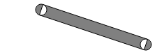
结果:

所以你已经得到它了。下面是我的最终代码,生成了一个漂亮的复合线段,可单击且可操作。
from PySide import QtGui, QtCore
import math
import sys
import weakref
from numpy import *
from PySide.QtGui import *
from PySide.QtCore import *


class Node(QGraphicsItem):
    Type = QGraphicsItem.UserType+1

    def __init__(self, graphWidget, line):

        super(self.__class__, self).__init__()
        self.line = line
        self.radius = 8

        if graphWidget != None:
            self.graph = weakref.ref(graphWidget)

        self.newPos = QPointF()
        self.setCacheMode(self.DeviceCoordinateCache)
        self.setZValue(-1)


    def boundingRect(self):
        adjust = 10.0
        x,y = array(self.line).transpose()
        rect = [min(x)-self.radius, min(y)-self.radius, max(x)-min(x)+2*self.radius, max(y)-min(y)+2*self.radius]

        return QRectF(*rect)

    def shape(self):
        path = QPainterPath()
        path.setFillRule(Qt.WindingFill)

        radius =  self.radius
        rotation = array( [[0,-1],[1,0]])

        points = zip(self.line[0:-1], self.line[1:])

        for p0, pn in points:
            (x0,y0),(xn,yn) = p0,pn
            dx,dy = array(pn) - array(p0)

            dV = array([dx,dy])
            mag_dV = linalg.norm(dV)

            v = dot(rotation, dV) * radius / mag_dV

            #starting circle
            path.addEllipse(QRectF(x0-radius, y0-radius, 2*radius, 2*radius))
            #rectangular part
            path.moveTo(QPointF(*p0-v))
            path.lineTo(QPointF(*pn-v))
            path.lineTo(QPointF(*pn+v))
            path.lineTo(QPointF(*p0+v))

        path.moveTo(QPointF(*pn))
        path.addEllipse(QRectF(xn-radius, yn-radius, 2*radius, 2*radius))

        return path.simplified()


    def paint(self, painter, option, widget):
        painter.setPen(Qt.black)
        painter.setBrush(Qt.darkGray)
        painter.setRenderHint(QPainter.Antialiasing)
        painter.drawPath(self.shape())

    def setGraph(self, graph):
        self.graph = weakref.ref(graph)

class GraphWidget(QGraphicsView):
    def __init__(self):
        super(self.__class__, self).__init__()

        self.timerId = 0

        scene = QGraphicsScene(self)
        scene.setItemIndexMethod(QGraphicsScene.NoIndex)
        scene.setSceneRect(0,0,880,880)
        self.setScene(scene)
        self.setCacheMode(QGraphicsView.CacheBackground)
        self.setRenderHint(QPainter.Antialiasing)
        self.setTransformationAnchor(QGraphicsView.AnchorUnderMouse)
        self.setResizeAnchor(QGraphicsView.AnchorViewCenter)

        self.centerNode = Node(self, [[50,50],[200,100], [500, 100], [700,700]])
        scene.addItem(self.centerNode)


        self.centerNode.setPos(0,0)
        self.setGeometry(100,100,900,900)
        self.setWindowTitle(self.tr("Elastic Nodes"))


    def addItem(self, item):
        self.item = item
        self.scene().addItem(item)
        item.setGraph(self)
        item.show()


if __name__ == "__main__":
    app = QApplication(sys.argv)
    qsrand(QTime(0,0,0).secsTo(QTime.currentTime()))

    widget = GraphWidget()
    widget.show()

    sys.exit(app.exec_())
关于python - 将 QPainterPath 简化为轮廓,我们在Stack Overflow上找到一个类似的问题: https://stackoverflow.com/questions/19528158/