我正在尝试在 HTML5 Canvas 中生成基本的瓷砖和楼梯,而不使用图像。
这是我到目前为止所做的:
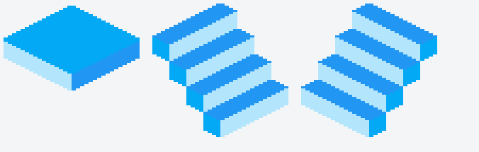
但我正在尝试重现这个:

我不知道该怎么做。
这是我当前的代码:
class IsometricGraphics {
    constructor(canvas, thickness) {
        this.Canvas = canvas;
        this.Context = canvas.getContext("2d");

        if(thickness) {
            this.thickness = thickness;
        } else {
            this.thickness = 2;
        }
    }

    LeftPanelWide(x, y, fillStyle) {
        this.Context.fillStyle = fillStyle;

        for(var i = 0; i < 16; i++) {
            this.Context.fillRect(x + i * 2, y + i * 1, 2, this.thickness * 4);
        }
    }

    RightPanelWide(x, y, fillStyle) {
        this.Context.fillStyle = fillStyle;

        for(var i = 0; i < 16; i++) {
            this.Context.fillRect(x + (i * 2), y + 15 - (i * 1), 2, this.thickness * 4);
        }
    }

    UpperPanelWide(x, y, fillStyle) {
        this.Context.fillStyle = fillStyle;

        for(var i = 0; i < 17; i++) {
            this.Context.fillRect(x + 16 + 16 - (i * 2), y + i - 2, i * 4, 1);
        }

        for(var i = 0; i < 16; i++) {
            this.Context.fillRect(x + i * 2, y + (32 / 2) - 1 + i, ((32 / 2) - i) * 4, 1);
        }
    }

    UpperPanelWideBorder(x, y, fillStyle) {
        this.Context.fillStyle = fillStyle;

        var y = y + 2;

        for(var i = 0; i < 17; i++) {
            this.Context.fillRect(x + 17 + 16 - (i * 2) - 2, y + i - 2, (i == 17) ? 1 : 2, 1);
            this.Context.fillRect(x + 17 + 16 + (i * 2) - 2, y + i - 2, (i == 17) ? 1 : 2, 1);
        }

        for(var i = 0; i < 32 / 2; i++) {
            this.Context.fillRect(x + i * 2, y + 16 - 1 + i, 2, 1);
            this.Context.fillRect(x + 62 - i * 2, y + 16 - 1 + i, 2, 1);
        }
    }

    RightUpperPanelSmall(x, y, fillStyle) {
        this.Context.fillStyle = fillStyle;

        for(var i = 0; i < 32 / 2 + 4; i++) {
            this.Context.fillRect(x + (i * 2), (i >= 4) ? (i - 1) + y : 3 - i + 3 + y, 2, (i >= 4) ? (i <= 20 - 5) ? 8 : (20 - i) * 2 - 1 : 1 + (i * 2));
        }
    }

    LeftUpperPanelSmall(x, y, fillStyle) {
        this.Context.fillStyle = fillStyle;

        for(var i = 0; i < 32 / 2 + 4; i++) {
            this.Context.fillRect(x + (i * 2), (i >= 16) ? y + (i - 16) : 16 + y - (i * 1) - 1, 2, (i >= 4) ? (i >= 16) ? 8 - (i - 16) - (i - 16) - 1 : 8 : 8 * i - (i * 6) + 1);
        }
    }

    LeftPanelSmall(x, y, fillStyle) {
        this.Context.fillStyle = fillStyle;

        for(var i = 0; i < 8 / 2; i++) {
            this.Context.fillRect(x + i * 2, y + i * 1, 2, this.thickness * 4);
        }
    }

    RightPanelSmall(x, y, fillStyle) {
        this.Context.fillStyle = fillStyle;

        for(var i = 0; i < 8 / 2; i++) {
            this.Context.fillRect(x + (i * 2), y + 3 - (i * 1), 2, this.thickness * 4);
        }
    }
}


class IsoGenerator {
    constructor() {
        var Canvas = document.querySelector("canvas");
        var Context = Canvas.getContext("2d");

        //Context.scale(5, 5);
        this.Context = Context;
        this.IsometricGraphics = new IsometricGraphics(Canvas, 2);
    }

    StairLeft(x, y, Color1, Color2, Color3) {
        for(var i = 0; i < 4; i++) {
            this.IsometricGraphics.RightPanelWide((x + 8) + (i * 8), (y + 4) + (i * 12), Color1);
            this.IsometricGraphics.LeftUpperPanelSmall(x + (i * 8), y + (i * 12), Color2);
            this.IsometricGraphics.LeftPanelSmall((i * 8) + x, (16 + (i * 12)) + y, Color3);
        }
    }

    StairRight(x, y, Color1, Color2, Color3) {
        for(var i = 0; i < 4; i++) {
            this.IsometricGraphics.LeftPanelWide(x + 24 - (i * 8), (4 + (i * 12)) + y, Color1);
            this.IsometricGraphics.RightUpperPanelSmall(x + 24 - (i * 8), y + (i * 12) - 3, Color2);
            this.IsometricGraphics.RightPanelSmall(x + 56 - (i * 8), (16 + (i * 12)) + y, Color3);
        }
    }

    Tile(x, y, Color1, Color2, Color3, Border) {
        this.IsometricGraphics.LeftPanelWide(x, 18 + y, Color1);
        this.IsometricGraphics.RightPanelWide(x + 32, 18 + y, Color2);
        this.IsometricGraphics.UpperPanelWide(x, 2 + y, Color3);

        if(Border) {
            this.IsometricGraphics.UpperPanelWideBorder(x, y, Border);
        }
    }
}

var Canvas = document.querySelector("canvas");
var Context = Canvas.getContext("2d");

Context.scale(3, 3);

new IsoGenerator().Tile(0, 0, "#B3E5FC", "#2196F3", "#03A9F4")
new IsoGenerator().StairLeft(70, 0, "#B3E5FC", "#2196F3", "#03A9F4")
new IsoGenerator().StairRight(70 * 2, 0, "#B3E5FC", "#2196F3", "#03A9F4")

// What I'm trying to reproduce: http://i.imgur.com/YF4xyz9.png
<canvas width="1000" height="1000"></canvas>fiddle :https://jsfiddle.net/xvak0jh1/2/
最佳答案
轴测图
处理轴测(通常称为等轴测)渲染的最佳方法是在 3D 中对对象进行建模,然后在您想要的特定轴测投影中渲染模型。
作为网格的 3D 对象
最简单的对象(在本例中)是一个盒子。该盒子有 6 个边和 8 个顶点,可以通过其顶点和将边表示为一组顶点索引的多边形来描述。
例如 3D 盒子,x 从左到右,y 从上到下,z 向上。
首先创建构成盒子的顶点
更新按照评论中的要求,我已将框更改为 x、y、z 尺寸。
// function creates a 3D point (vertex)
function vertex(x,y,z){ return {x,y,z} };
// an array of vertices
const vertices = []; // an array of vertices

// create the 8 vertices that make up a box

const boxSizeX = 10;   // size of the box x axis
const boxSizeY = 50;   // size of the box y axis
const boxSizeZ = 8;   // size of the box z axis
const hx = boxSizeX / 2; // half size shorthand for easier typing
const hy = boxSizeY / 2;
const hz = boxSizeZ / 2;

vertices.push(vertex(-hx,-hy,-hz)); // lower top left  index 0
vertices.push(vertex( hx,-hy,-hz)); // lower top right
vertices.push(vertex( hx, hy,-hz)); // lower bottom right
vertices.push(vertex(-hx, hy,-hz)); // lower bottom left
vertices.push(vertex(-hx,-hy, hz)); // upper top left  index 4
vertices.push(vertex( hx,-hy, hz)); // upper top right
vertices.push(vertex( hx, hy, hz)); // upper bottom right
vertices.push(vertex(-hx, hy, hz)); // upper  bottom left index 7
然后为盒子上的每个面创建多边形
const colours = {
    dark : "#444",
    shade : "#666",
    light : "#aaa",
    bright : "#eee",
}
function createPoly(indexes,colour){ return { indexes, colour} }
const polygons = [];
// always make the polygon vertices indexes in a clockwise direction
// when looking at the polygon from the outside of the object
polygons.push(createPoly([3,2,1,0],colours.dark)); // bottom face
polygons.push(createPoly([0,1,5,4],colours.dark)); // back face
polygons.push(createPoly([1,2,6,5],colours.shade)); // right face
polygons.push(createPoly([2,3,7,6],colours.light)); // front face
polygons.push(createPoly([3,0,4,7],colours.dark)); // left face
polygons.push(createPoly([4,5,6,7],colours.bright)); // top face
现在您有了一个包含 6 个多边形的盒子的 3D 模型。
投影
投影描述了 3D 对象如何转换为 2D 投影。这是通过为每个 3D 坐标提供一个 2D 轴来完成的。
在本例中,您使用的是双等投影的修改版
因此,让我们为 3 个 3D 坐标中的每一个定义 2D 轴。
  // From here in I use P2,P3 to create 2D and 3D points
  const P3 = (x=0, y=0, z=0) => ({x,y,z});
  const P2 = (x=0, y=0) => ({x, y});

  // an object to handle the projection
  const isoProjMat = {
      xAxis : P2(1 , 0.5) ,  // 3D x axis for every 1 pixel in x go down half a pixel in y
      yAxis :  P2(-1 , 0.5) , // 3D y axis for every -1 pixel in x go down half a pixel in y
      zAxis :  P2(0 , -1) , // 3D z axis go up 1 pixels
      origin : P2(100,100),  // where on the screen 3D coordinate (0,0,0) will be
现在定义通过将 x,y,z (3d) 坐标转换为 x,y (2d) 进行投影的函数
      project (p, retP = P2()) {
          retP.x = p.x * this.xAxis.x + p.y * this.yAxis.x + p.z * this.zAxis.x + this.origin.x;
          retP.y = p.x * this.xAxis.y + p.y * this.yAxis.y + p.z * this.zAxis.y + this.origin.y;
          return retP;
      }
  }
渲染
现在您可以渲染模型了。首先,您必须将每个顶点投影到 2D 屏幕坐标中。
// create a new array of 2D projected verts
const projVerts = vertices.map(vert => isoProjMat.project(vert));
然后只需通过索引将每个多边形渲染到 projVerts 数组
polygons.forEach(poly => {
    ctx.fillStyle = poly.colour;
    ctx.beginPath();
    poly.indexs.forEach(index => ctx.lineTo(projVerts[index].x, projVerts[index].y) );
    ctx.fill();
});
作为片段
const ctx = canvas.getContext("2d");

// function creates a 3D point (vertex)
function vertex(x, y, z) { return { x, y, z}};
// an array of vertices
const vertices = []; // an array of vertices

// create the 8 vertices that make up a box
const boxSizeX = 10 * 4;   // size of the box x axis
const boxSizeY = 50 * 4;   // size of the box y axis
const boxSizeZ = 8 * 4;   // size of the box z axis
const hx = boxSizeX / 2; // half size shorthand for easier typing
const hy = boxSizeY / 2;
const hz = boxSizeZ / 2;

vertices.push(vertex(-hx,-hy,-hz)); // lower top left  index 0
vertices.push(vertex( hx,-hy,-hz)); // lower top right
vertices.push(vertex( hx, hy,-hz)); // lower bottom right
vertices.push(vertex(-hx, hy,-hz)); // lower bottom left
vertices.push(vertex(-hx,-hy, hz)); // upper top left  index 4
vertices.push(vertex( hx,-hy, hz)); // upper top right
vertices.push(vertex( hx, hy, hz)); // upper bottom right
vertices.push(vertex(-hx, hy, hz)); // upper  bottom left index 7


const colours = {
  dark: "#444",
  shade: "#666",
  light: "#aaa",
  bright: "#eee",
}

function createPoly(indexes, colour) {
  return {
    indexes,
    colour
  }
}
const polygons = [];
// always make the polygon vertices indexes in a clockwise direction
// when looking at the polygon from the outside of the object
polygons.push(createPoly([3, 2, 1, 0], colours.dark)); // bottom face
polygons.push(createPoly([0, 1, 5, 4], colours.dark)); // back face
polygons.push(createPoly([3, 0, 4, 7], colours.dark)); // left face
polygons.push(createPoly([1, 2, 6, 5], colours.shade)); // right face
polygons.push(createPoly([2, 3, 7, 6], colours.light)); // front face
polygons.push(createPoly([4, 5, 6, 7], colours.bright)); // top face


// From here in I use P2,P3 to create 2D and 3D points
const P3 = (x = 0, y = 0, z = 0) => ({x,y,z});
const P2 = (x = 0, y = 0) => ({ x, y});

// an object to handle the projection
const isoProjMat = {
  xAxis: P2(1, 0.5), // 3D x axis for every 1 pixel in x go down half a pixel in y
  yAxis: P2(-1, 0.5), // 3D y axis for every -1 pixel in x go down half a pixel in y
  zAxis: P2(0, -1), // 3D z axis go up 1 pixels
  origin: P2(150, 75), // where on the screen 3D coordinate (0,0,0) will be
  project(p, retP = P2()) {
    retP.x = p.x * this.xAxis.x + p.y * this.yAxis.x + p.z * this.zAxis.x + this.origin.x;
    retP.y = p.x * this.xAxis.y + p.y * this.yAxis.y + p.z * this.zAxis.y + this.origin.y;
    return retP;
  }
}

// create a new array of 2D projected verts
const projVerts = vertices.map(vert => isoProjMat.project(vert));
// and render
polygons.forEach(poly => {
  ctx.fillStyle = poly.colour;
  ctx.beginPath();
  poly.indexes.forEach(index => ctx.lineTo(projVerts[index].x, projVerts[index].y));
  ctx.fill();
});
canvas {
border: 2px solid black;
}<canvas id="canvas"></canvas>更多
这是基础知识,但绝不是全部。我通过确保多边形的顺序在距观看者的距离方面是正确的来作弊。确保较远的多边形不会绘制在较近的多边形之上。对于更复杂的形状,您将需要添加深度排序。您还希望通过不绘制背向观察者的面(多边形)来优化渲染。这称为背面剔除。
您还需要添加照明模型等等。
像素双等投影。
上面的内容其实并不是你想要的。在游戏中,您使用的投影通常称为像素艺术投影,它不适合良好的数学投影。有许多关于抗锯齿的规则集,其中顶点根据面的方向进行渲染。
例如,根据面部方向,在像素上、左或上、右、或下、右或下、左绘制顶点,并在奇数和偶数 x 坐标之间交替,仅举几个规则
这支笔Axonometric Text Render (AKA Isometric)是轴测渲染的一个稍微复杂的示例,它具有 8 个常见轴测投影的选项,并包括简单的深度排序,尽管不是为了速度而构建的。 This answer这就是我写笔的灵感来源。
你的形状。
毕竟,下一个片段通过将基本框移动到每个位置并按从后到前的顺序渲染它来绘制您想要的形状。
const ctx = canvas.getContext("2d");

// function creates a 3D point (vertex)
function vertex(x, y, z) { return { x, y, z}};
// an array of vertices
const vertices = []; // an array of vertices

// create the 8 vertices that make up a box
const boxSize = 20; // size of the box
const hs = boxSize / 2; // half size shorthand for easier typing

vertices.push(vertex(-hs, -hs, -hs)); // lower top left  index 0
vertices.push(vertex(hs, -hs, -hs)); // lower top right
vertices.push(vertex(hs, hs, -hs)); // lower bottom right
vertices.push(vertex(-hs, hs, -hs)); // lower bottom left
vertices.push(vertex(-hs, -hs, hs)); // upper top left  index 4
vertices.push(vertex(hs, -hs, hs)); // upper top right
vertices.push(vertex(hs, hs, hs)); // upper bottom right
vertices.push(vertex(-hs, hs, hs)); // upper  bottom left index 7


const colours = {
  dark: "#004",
  shade: "#036",
  light: "#0ad",
  bright: "#0ee",
}

function createPoly(indexes, colour) {
  return {
    indexes,
    colour
  }
}
const polygons = [];
// always make the polygon vertices indexes in a clockwise direction
// when looking at the polygon from the outside of the object
//polygons.push(createPoly([3, 2, 1, 0], colours.dark)); // bottom face
//polygons.push(createPoly([0, 1, 5, 4], colours.dark)); // back face
//polygons.push(createPoly([3, 0, 4, 7], colours.dark)); // left face
polygons.push(createPoly([1, 2, 6, 5], colours.shade)); // right face
polygons.push(createPoly([2, 3, 7, 6], colours.light)); // front face
polygons.push(createPoly([4, 5, 6, 7], colours.bright)); // top face


// From here in I use P2,P3 to create 2D and 3D points
const P3 = (x = 0, y = 0, z = 0) => ({x,y,z});
const P2 = (x = 0, y = 0) => ({ x, y});

// an object to handle the projection
const isoProjMat = {
  xAxis: P2(1, 0.5), // 3D x axis for every 1 pixel in x go down half a pixel in y
  yAxis: P2(-1, 0.5), // 3D y axis for every -1 pixel in x go down half a pixel in y
  zAxis: P2(0, -1), // 3D z axis go up 1 pixels
  origin: P2(150, 55), // where on the screen 3D coordinate (0,0,0) will be
  project(p, retP = P2()) {
    retP.x = p.x * this.xAxis.x + p.y * this.yAxis.x + p.z * this.zAxis.x + this.origin.x;
    retP.y = p.x * this.xAxis.y + p.y * this.yAxis.y + p.z * this.zAxis.y + this.origin.y;
    return retP;
  }
}
var x,y,z;
for(z = 0; z < 4; z++){
   const hz = z/2;
   for(y = hz; y < 4-hz; y++){
       for(x = hz; x < 4-hz; x++){
          // move the box
          const translated = vertices.map(vert => {
               return P3(
                   vert.x + x * boxSize,
                   vert.y + y * boxSize,
                   vert.z + z * boxSize,
               );
          });

          // create a new array of 2D projected verts
          const projVerts = translated.map(vert => isoProjMat.project(vert));
          // and render
          polygons.forEach(poly => {
            ctx.fillStyle = poly.colour;
            ctx.strokeStyle = poly.colour;
            ctx.lineWidth = 1;
            ctx.beginPath();
            poly.indexes.forEach(index => ctx.lineTo(projVerts[index].x , projVerts[index].y));
            ctx.stroke();
            ctx.fill();

          });
      }
   }
}
canvas {
border: 2px solid black;
}<canvas id="canvas"></canvas>关于javascript - HTML5 Canvas 生成等距图 block ,我们在Stack Overflow上找到一个类似的问题: https://stackoverflow.com/questions/44835310/